


First Angle vs Third Angle Projection: Key Differences in Engineering Drawings
First Angle vs Third Angle Projection in Mechanical Drawings
In CNC precision machining, understanding engineering drawings is essential for accurate part manufacturing. One common challenge, especially for beginners, is distinguishing between first angle projection and third angle projection.
These two projection methods are widely used in mechanical drawings, but they follow different conventions for arranging views. Misinterpreting them can lead to machining errors and costly rework.
This article explains the key differences between first angle and third angle projection in a simple and practical way.
What Is the Main Difference?
The fundamental difference lies in the relative position of the object, the observer, and the projection plane.
First Angle Projection Explained
In first angle projection, the object is located between the observer and the projection plane.
View Arrangement:
- Front view: center
- Left view: placed on the right side
- Right view: placed on the left side
- Top view: placed below
- Bottom view: placed above
- Rear view: usually placed on the far right
This layout may feel counterintuitive for beginners because the views are “mirrored.”![]()
![]()
Third Angle Projection Explained
In third angle projection, the projection plane is located between the observer and the object.
View Arrangement:
- Front view: center
- Left view: placed on the left side
- Right view: placed on the right side
- Top view: placed above
- Bottom view: placed below
- Rear view: can be placed on either side
This method is more intuitive because the views correspond directly to their actual positions.
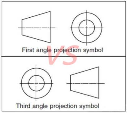
Projection Symbols in Engineering Drawings
Engineering drawings usually include a projection symbol to indicate which method is used:
- First angle projection symbol
- Third angle projection symbol
These symbols are essential because the drawing layout alone may not always be sufficient to identify the projection method.
Countries Using Each Projection Method
Different countries follow different standards:
First Angle Projection Countries:
- China
- United Kingdom
- Germany
- France
- Russia
Third Angle Projection Countries:
- United States
- Japan
- Australia
- Canada
When working with international clients in CNC machining services, always confirm the projection standard used in the drawings.
Why This Matters in CNC Machining
Correctly interpreting projection methods is critical because:
- It ensures dimensional accuracy
- Prevents machining errors
- Reduces communication issues with global clients
- Improves production efficiency
Even a small misunderstanding in view orientation can result in incorrect part geometry.
FAQ – First Angle vs Third Angle Projection
1. What is the easiest way to tell the difference?
Check the projection symbol on the drawing. It clearly indicates whether it is first angle or third angle projection.
2. Which projection is more commonly used?
- First angle projection is common in Europe and Asia
- Third angle projection is standard in North America
3. Why do different countries use different systems?
These standards developed historically and are maintained by regional engineering conventions.
Conclusion
Understanding the difference between first angle and third angle projection is essential for anyone working with engineering drawings and CNC machining.
By recognizing view arrangements and projection symbols, manufacturers can avoid costly mistakes and ensure accurate production.
Need help interpreting engineering drawings or manufacturing precision parts?
Contact us today for reliable CNC machining services and expert technical support.


