


LiDAR CNC Machining: Key Considerations for Precision Machined Parts
Key Considerations for CNC Machining LiDAR Parts
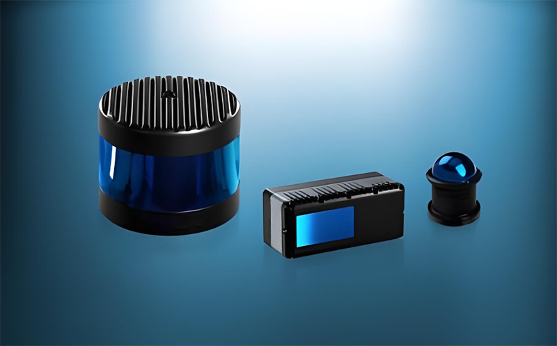
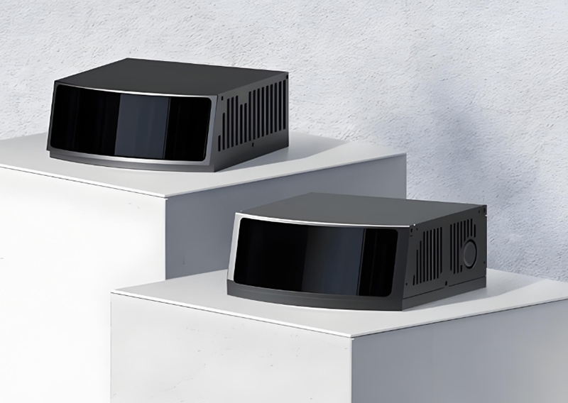
LiDAR (Light Detection and Ranging) systems are widely used in autonomous vehicles, robotics, drones, surveying equipment, and industrial automation. These systems rely on highly precise optical and mechanical assemblies, making CNC machining a critical process in the production of LiDAR housings, mounts, and structural components.
When machining LiDAR parts, manufacturers must pay close attention to dimensional accuracy, material stability, surface finish, and sealing performance. Even the smallest deviation can affect optical alignment, distort signal transmission, or compromise the device’s reliability in harsh environments.
Precision: The Foundation of Optical Alignment
Typical Precision Requirements
· Critical dimensional tolerances: ±0.005 mm to ±0.015 mm
· Flatness: within 0.01 mm per 100 mm
· Position and concentricity tolerances for optical mounting features
· Use high-precision CNC machining centers with closed-loop linear scale feedback
· Prefer 5-axis machining to reduce errors caused by multiple setups
· Perform in-process and final inspection using Coordinate Measuring Machines (CMM)
Material Selection and Stress Relief
Common Materials for LiDAR Components
Aluminum Alloys (6061-T6 and 7075-T6)
Engineering Plastics (PPS, PEEK, PTFE)
A recommended production workflow is:
Rough Machining → Stress Relief Heat Treatment → Finish Machining
Surface Finish: Critical for Optical Performance and Sealing
Surface quality directly affects optical alignment and sealing effectiveness.
Surface Roughness Requirements
· Optical mounting and sealing surfaces: Ra ≤ 0.4 μm
· General structural surfaces: Ra ≤ 0.8 μm
· Use sharp ball nose or finishing end mills
· High spindle speeds (8,000–12,000 rpm for aluminum)
· Small feed rates and optimized toolpaths
· Multi-stage machining: roughing, semi-finishing, and finishing
Sealing Performance and IP Protection
LiDAR units used outdoors must withstand water, dust, and temperature fluctuations.
Requirements for IP67/IP68 Housings
· Sealing surface roughness: Ra 0.4–0.8 μm
· O-ring groove depth tolerance: ±0.01 mm
· Flatness of mating surfaces: 0.01 mm/100 mm
These specifications ensure even compression of seals and long-term waterproof reliability.
Improper clamping can deform thin-wall LiDAR components.
Recommended Workholding Methods
· Aluminum: polished carbide tools to prevent built-up edge
· Stainless steel and titanium: TiAlN-coated tools with high-pressure coolant
Quality Control and Process Monitoring
Final inspection alone is not enough for precision LiDAR components.
· On-machine probing for real-time compensation
· In-process dimensional checks
· Full traceability from raw material to shipment
· First Article Inspection (FAI) and inspection reports
Why CNC Machining Quality Matters for LiDAR Systems
Selecting an experienced CNC machining supplier is essential to ensure reliability and consistent performance.
CNC Machining Solutions for LiDAR Components
At XSH Precision, we specialize in manufacturing high-precision LiDAR parts, including:
· Prototype and production quantities
Request a Quote for LiDAR CNC Machining
Looking for a reliable supplier for precision LiDAR components?
Send us your drawings (STEP, STP, IGS, PDF) for a fast quotation and professional DFM support. XSH Precision delivers cost-effective, high-accuracy CNC machined parts for demanding LiDAR applications worldwide.


